This is part 2 of my Gigabyte R281-T91 ARM64 server unboxing and installation. In this post we will be installing some basic hardware components so that the server can be booted up and have an operating system installed. I purchased this as a bare bones system from ThunderXForums. They offer workstations, motherboards, and other server form factors for the ARM64 platform.
Oops!
Uh-oh... It looks like I forgot to screw the rails on to the rack. I found these two screws in the little plastic bag that was supplied with the rail installation kit. Extra parts are usually not a good sign.
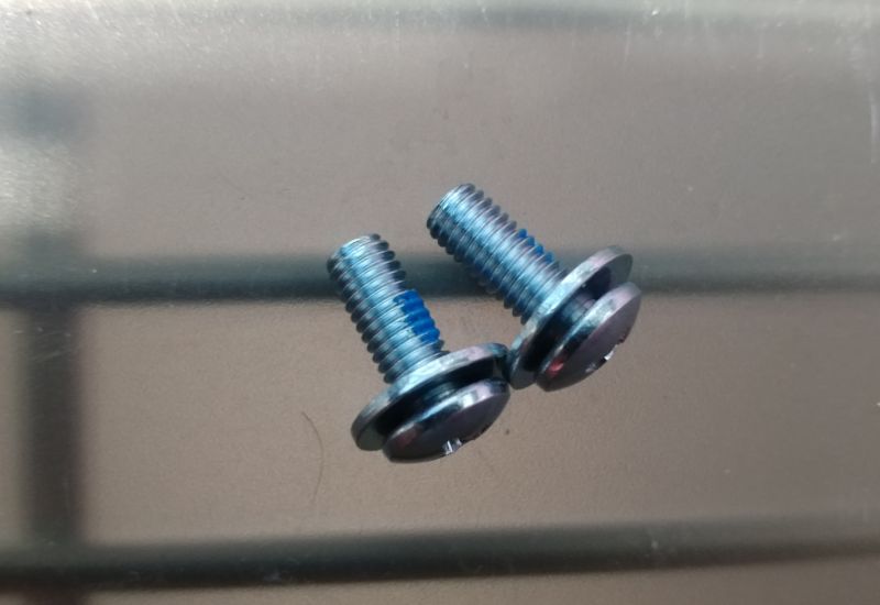
Even though the rails are security locked in place, there are two security screws that need to be put in for additional protection. So that the entire thing doesn't fall down should something be moved out of place to far.
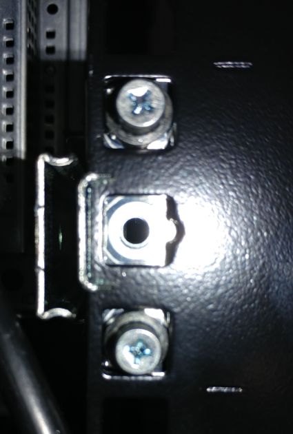
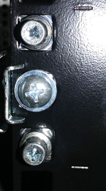
What a mess this would have been.
Hardware Installation
I purchased some basic components to have a minimum functioning system. Overtime I'll add and upgrade parts as needed. The SSD's are two consumer grade PNY CS900 120GB 2.5inch SATA drives. They will be used only for the operating system and I don't plan on keeping anything valuable on them. I'll have backups setup just in case I need to restore configuration or rebuild anything. The network adapter does not use your average RJ45 twisted pair copper Ethernet connector. Instead it's an SFP+ port for which we'll need some SFP to 1.25G Ethernet adapters.
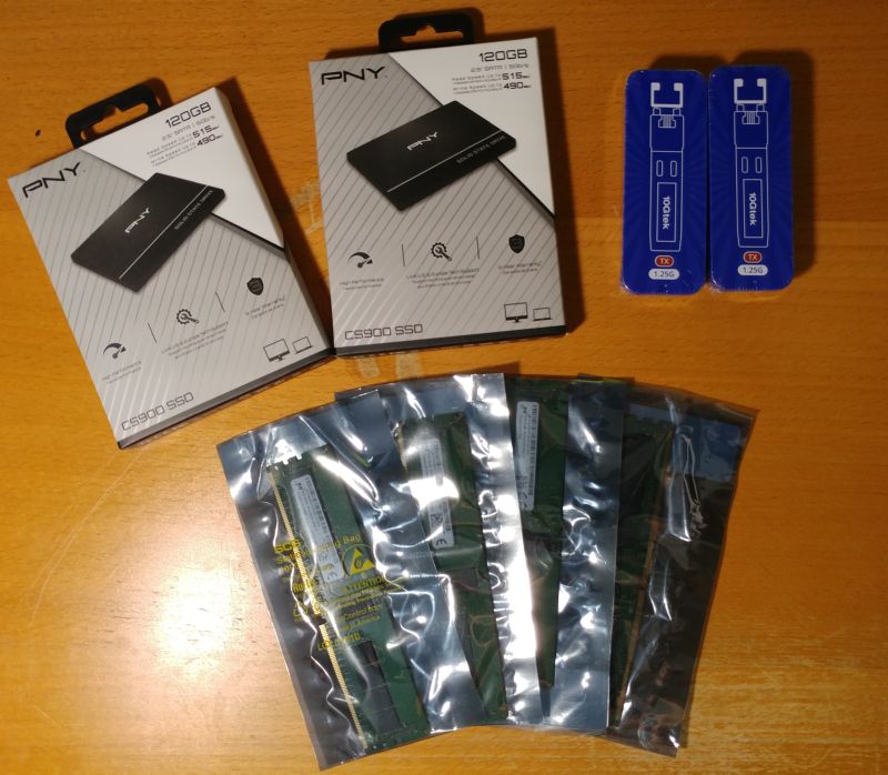
The server uses (as expected) registered DDR4 SDRAM. I was able to find a few of them on eBay that are compatible with this system for a reasonable cost. There is no special RAM module properties for an ARM system as opposed to an x86 system. As long as your memory meets the requirements, it will work.
Memory
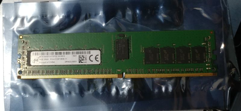
I will be going with the absolute minimum of 32 GB. Each CPU requires at least two modules and the minimum module size is 8GB. Finding reasonably priced memory that meets the requirments for this server is no easy task. After several days of searching I was able to get four 288-pin Micron 8 GB DDR4 SDRAM Modules at 2133 MHz. The part number is MTA18ASF1G72PDZ-2G1B1.
There is a specific order to installing the memory and it was difficult to figure out from the manual. The manual provides an image of each slot labeled with a letter and a number, but makes no mention of the order it should be populated. The only part that is obvious is the processor number (P0 and P1). Take a closer look at the image below. First glance you think it makes sense, but then it gets confusing.
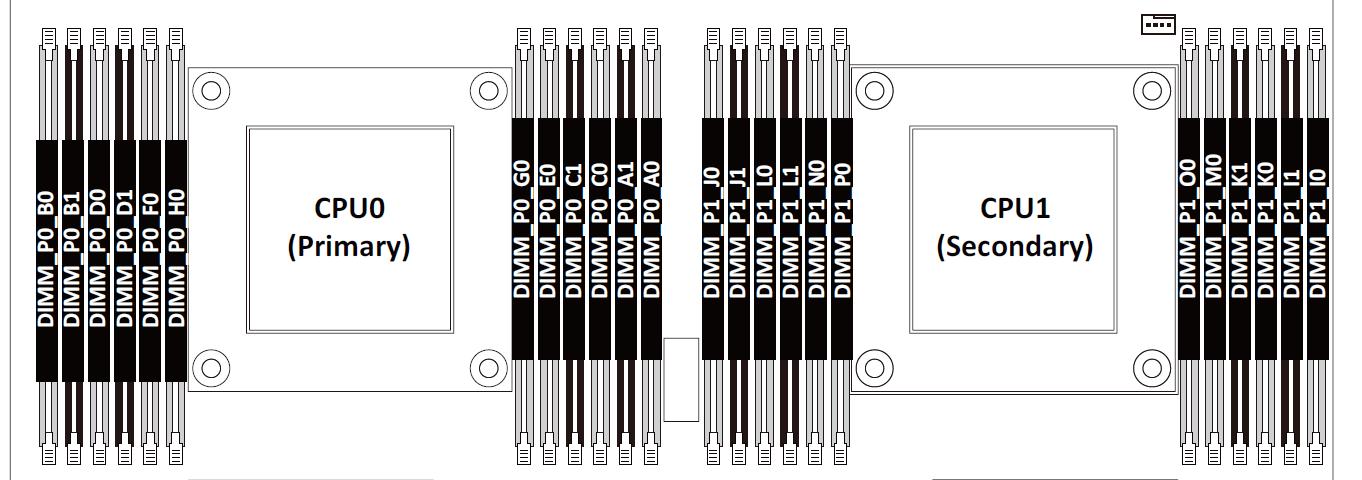
There is some color coding on the slots, but that doesn't help at all.
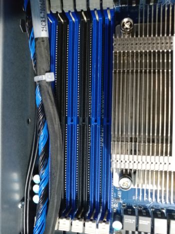
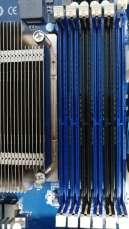
I had to resort to some online research on how to install dual channel DDR4 memory. Thankfully there are some guides available and the process seems to be pretty standard. This particular guide on installing dual channel memory[1] was a good source for some theory, but still didn't get me what I needed. After lots of trial and error and further research I finally came to understand the correct 'way'.
Memory is installed evenly per CPU from the outermost slots inward. Starting with the blue slots first, then populating the black slots prior to populating the 4 inner blue slots. In other words, the 4 inner blue slots nearest the CPU get populated only after the outer black and blue slots are populated with DIMMS.
First 4 DIMMS
- DIMM_P0_A0
- DIMM_P0_B0
- DIMM_P1_I0
- DIMM_P1_J0
Next 4 DIMMS (8 total)
- DIMM_P0_C0
- DIMM_P0_D0
- DIMM_P1_K0
- DIMM_P1_L0
Next 4 DIMMS (12 total)
- DIMM_P0_A1
- DIMM_P0_B1
- DIMM_P1_I1
- DIMM_P1_J1
Next 4 DIMMS (16 total)
- DIMM_P0_C1
- DIMM_P0_D1
- DIMM_P1_K1
- DIMM_P1_L1
Remaining 8 DIMMS (24 total)
You must install the remaining 8 DIMMS all at once. You can't install 4 at a time.
- DIMM_P0_E0
- DIMM_P0_F0
- DIMM_P0_G0
- DIMM_P0_H0
- DIMM_P1_M0
- DIMM_P1_N0
- DIMM_P1_O0
- DIMM_P1_P0
Below is a picture of the primary CPU. Modules are installed in A0 and B0. The other CPU has it's memory modules installed in I0 and J0.
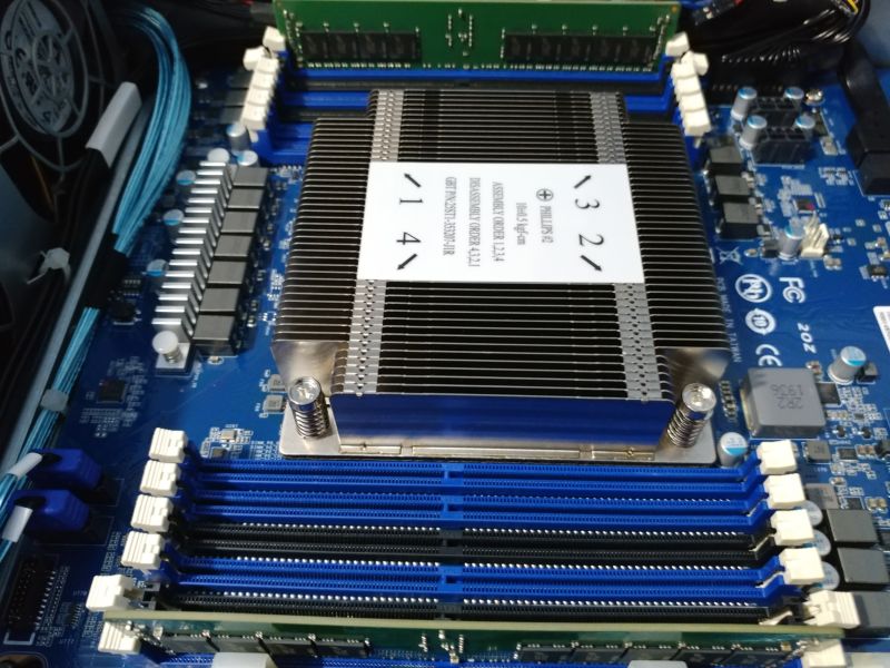
This was the hardest part in my opinion. I still don't fully understand the logic behind the labels. Normally there would be clear instructions on the order in which you populate the modules, saying exactly what slot to put the next module in.
Storage
Next up is the storage volume for the operating system. The plan is to use FreeBSD ZFS on root with mirrored SSD's. 120 GB is more than enough space for the operating system.
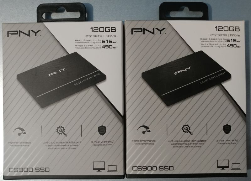
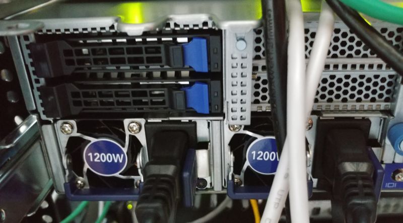
I think it's clever how the server has a special place for these SSD's in the back exactly for this purpose. It's even hot swap-able.
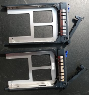
The trays are tool-less and the SSD's just snap into place.
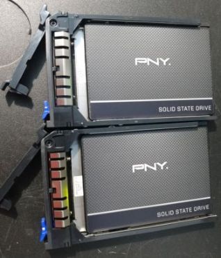
These SSD's are using the normal consumer grade SATA interface.
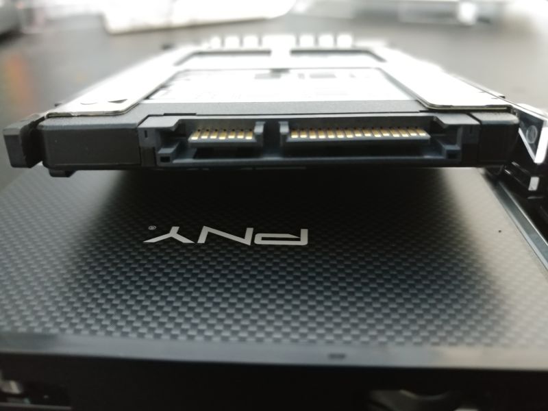
That's a nice picture right?
Networking
As mentioned this is not your average network interface with RJ45 connectors. This particular adapter, a "FastLinQ QL41000 Series 10/25/40/50GbE Controller" has several connectivity options via it's SFP+ ports (L1 and L2 on the left). You can use a direct connect copper cable, twisted pair copper (ie. CAT5e), or fiber.
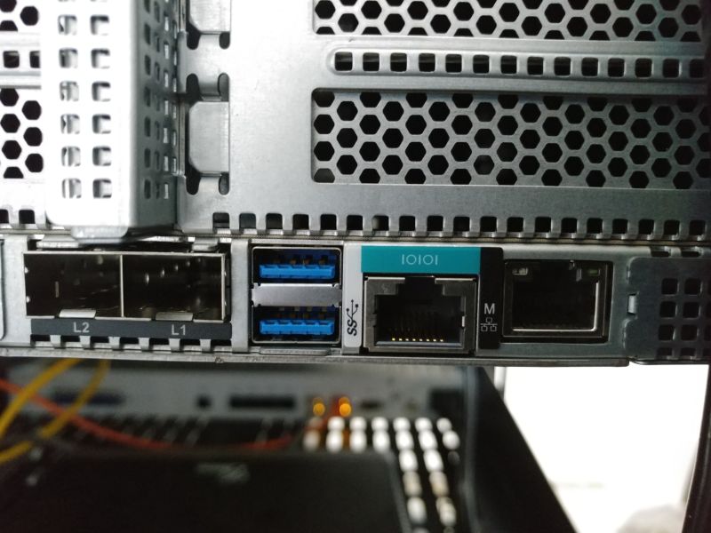
Although my NETGEAR GSM7352S can support all those options, I will keep it simple and use SFP to 1.25G Ethernet adapters. These are fairly inexpensive and are (for my purposes) enough. In the future I might upgrade to direct copper or fiber.
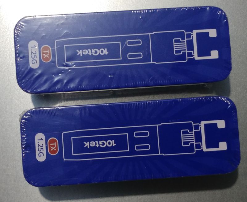
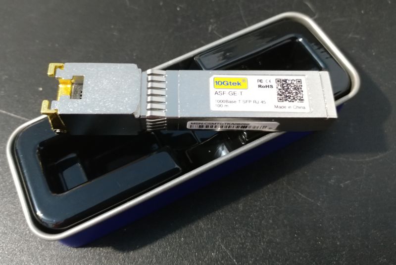
This is the first time I've ever worked with this type of hardware, but they are easy to install.
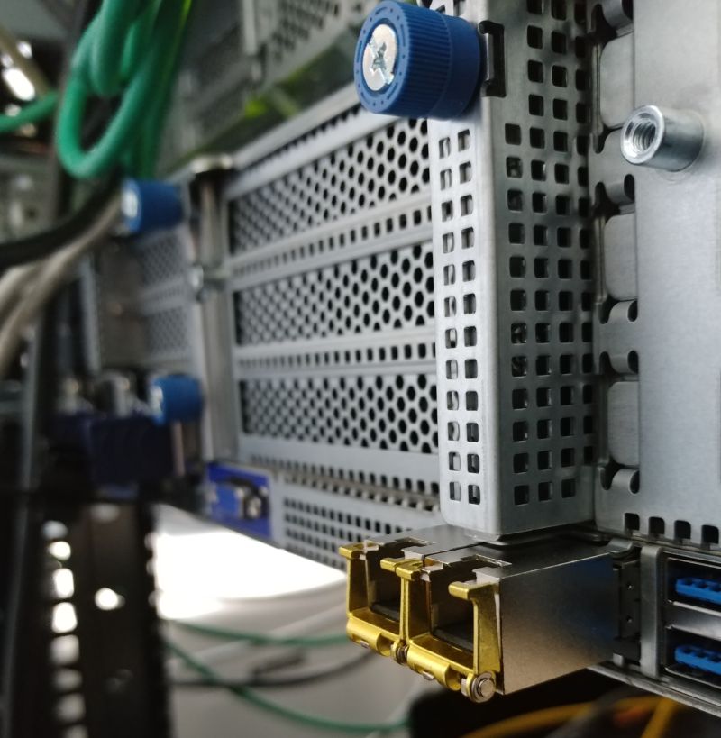
That should be it. Lets re-rack the server and power it on.
MegaRAC SP-X Management Console
The R281-T91 like all great servers these days has a built-in BMC that supports both IPMI and the newer Redfish standard. For this server it is implemented by American Megatrends MegaRAC firmware.
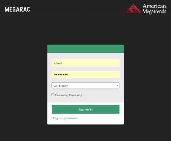
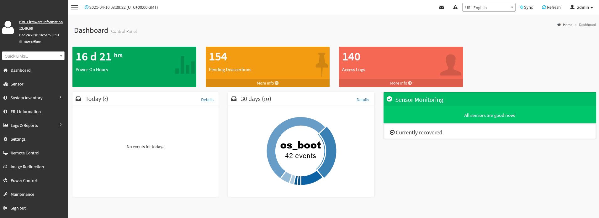
The dashboard isn't very impressive and reminds me of one of those out-of-the-box bootstrap admin panel templates. The menu items on the left are pretty basic. As someone who's worked primarily with Lenovo and IBM's IMM, this is pretty much the expected set of functions.
Lets take a quick look at the hardware inventory, starting with the CPU. Click on the image below to show the full expanded view.
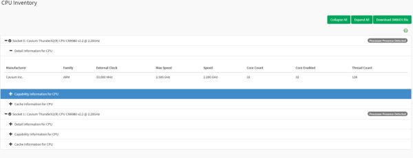
Yep, it's two Cavium ThunderX2(R) CPU CN9980 v2.2 @ 2.20GHz. Each one has 32 cores and 128 threads. So this would show up as 256 CPU's in our FreeBSD OS, that should be interesting.
Lets check the system inventory to see if our memory is being properly recognized.
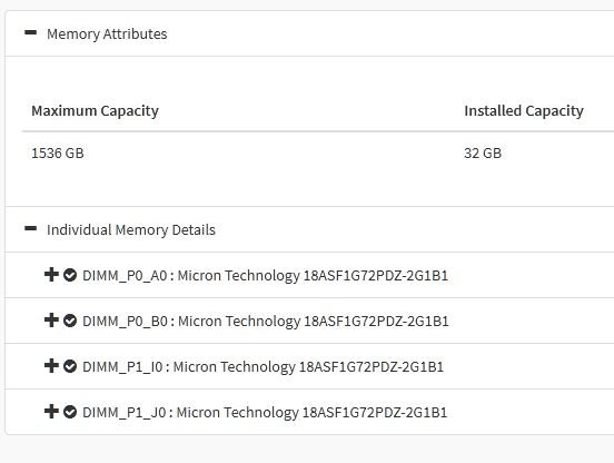
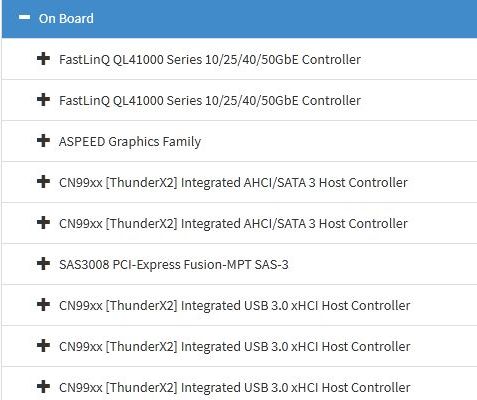
This inventory feature is actually quite informative. It really gives you exact details of what is installed. Looking at the PCI Inventory we can see the type of network, video, and storage controllers we have.
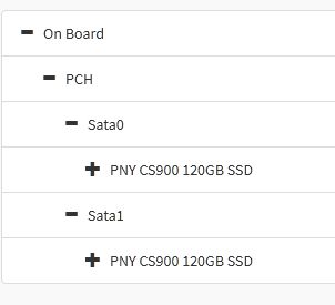
Finally, we can see our SSD's
I won't go through every menu item and section, besides the power controls, remote storage and logs, the other interesting area is the remote control. Both a Java based and HTML5 based viewer are available as the remote KVM UI. The serial over LAN option looks useful as well.
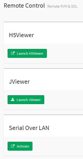
There is just so much to explore.
Powering On
I'll use the HTML5 option for my first power up.
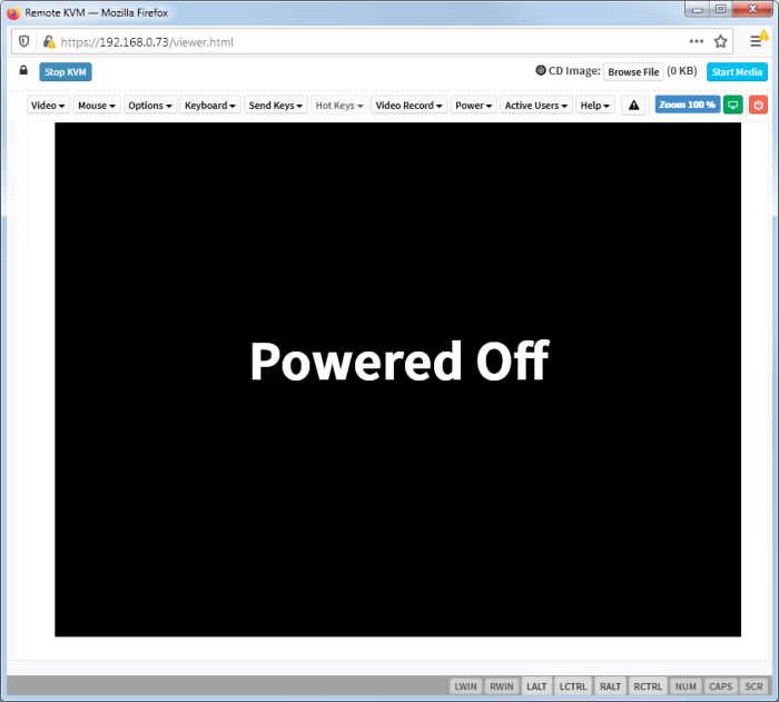
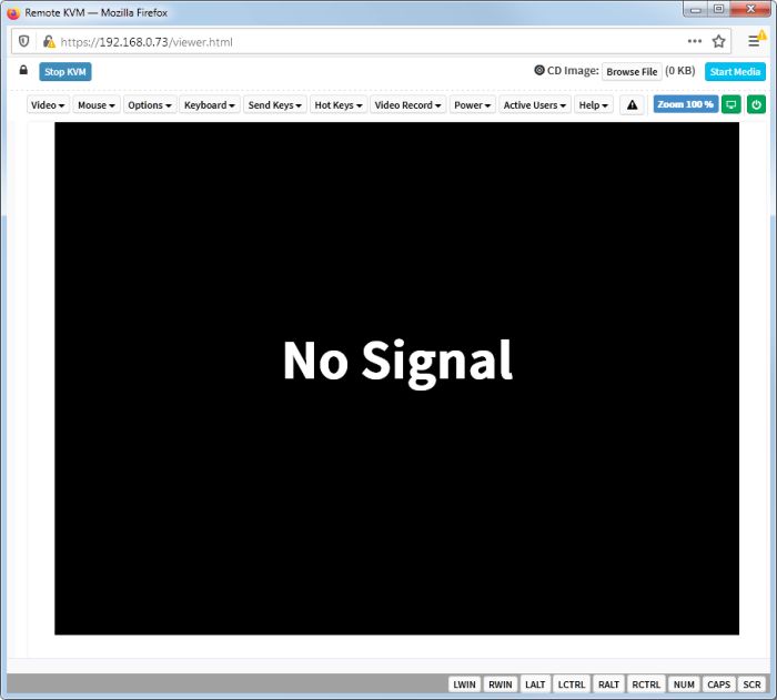
It takes a while for anything to show up on screen. Several minutes pass and the screen just sits there with "No Signal".
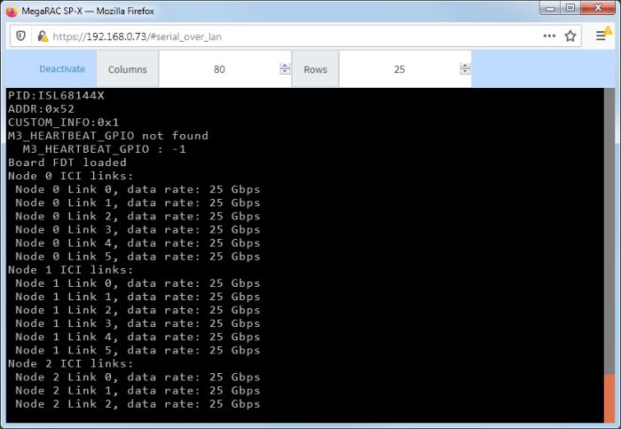
Looking at the Serial Over LAN option reveals that stuff is indeed going on in the background. The system is running through it's initialization process. This is expected on ARM. If you've ever used a Raspberry PI this behavior will be very familiar. ARM platform's don't boot in the same way as an x86 machine.
However, the boot process for ARM servers is slightly different and indeed includes the familiar "BIOS" screen that is actually an UEFI application[2]. After waiting long enough we see a GIGABYTE logo with options to select a boot device or enter the setup.
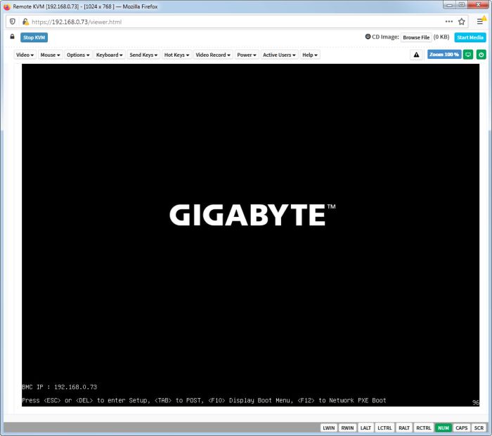
Since there is no OS installed, this will probably error out or just go on a boot loop.
Look out for part 3 where we try to not just boot FreeBSD, but also install it.
[1] Many thanks and credit to the original author at compuram for writing that guide.
[2] Check out the first part of this article for a brief intro on the subject and wiki for a full explanation..
- Log in to post comments


.png)